


Anchoring spiralling cable costs
Downloads
| Anchoring-spiralling-cable-costs.pdf ( PDF 790KB) |
The cost of cables is rising in manufacturing as the result of the need for lengthy shielded cable to tackle attenuation and electromagnetic compatibility (EMC) issues.
Compounded by increasing commodity prices, this is leading many original equipment manufacturers (OEMs) to look for cost effective solutions. Here Steve Hughes, managing director of REO UK, explores how OEMs can anchor spiralling cable costs using sine wave filters.
The modern day cable; regardless of whether we love it or hate it, we could not live without it. From tangled headphones and messy home theatre setups, to travel infrastructure and mission critical manufacturing applications, there is no doubt that the humble cable is a necessity in modern society.
The cable may be modern, but the word is certainly not. Originating in the age of sail, the term ‘cable length’ was given to the length of a ships anchor, which in time standardised to become the generally accepted length of a nautical mile. Despite the word having weathered the subsequent centuries, traditional sailing ships were ultimately made obsolete with the advent of steam powered vessels.
Similarly, wireless connectivity such as Wi-Fi and induction charging is the disruptive technology of our age. Nevertheless, it is yet to replace, the need for physical cabling in manufacturing industries throughout the world.
This need for cabling is evidenced by the recent €600m NorNed high voltage direct current (HVDC) submarine power cable that runs between Norway and the Netherlands. At 360 miles long, it is the world’s longest underwater cable.
Although not quite as long, the demand for cable lengths in industrial environments can be high. Variable speed drives (VSDs) and long cable runs, over 50m between the VSD and the motor are common, but can conspire to create further electrical interference.
Three phase induction motor control has been greatly enhanced in recent years by the use of VSDs. The rotary speed of the induction motor can be easily manipulated by altering the frequency of the supply current. The result is a fixed voltage, variable frequency output. Although the benefit of the VSD is to lower cost by increasing efficiency, the process has some drawbacks.
Pulse width modulation (PWM), the process used to switch the VSD inverter – typically between 8-16 kHz, produces a series of output pulses that average to a sine wave. The power conversion process creates unwanted frequency components such as harmonic currents, which, in substantive quantities, can lead to electromagnetic interference (EMI).
The degradation caused by EMI can be significant and varied, wearing down the ability of components to operate at optimal performance and potentially even lead to machine failure. The damage ranges from overheating transformers, windings and capacitors, to interference affecting telecommunication equipment and metering apparatus.
As well as this, excessive currents in the neutral cable of a three phase system and high voltage fluctuations, known as electrical flicker, can affect the supply for domestic users on public low voltage networks or OEMs on industrial networks.
Continuous and problematic levels of EMI can constitute electromagnetic compatibility (EMC) issues, rendering some equipment unsafe to use. Standards set at European level, dictate the minimum requirements for safe usage of VSDs in power drive systems (PDS). IEC/EN 61800-3 directives apply to manufacturers, panel builders and systems integrators.
The purpose of these directives is to minimise harmonics, demand the assessment of all connected equipment prior to use and provide sufficient technical documentation for all users.
Further practical requirements aim to improve conduction and reduce radiation based emissions – as well as reduce the high voltage differences (dv/dt) generated from the high frequency switching of insulated-gate bipolar transistors (IGBT). Consequently, minimum requirements have been set for cabinet grounding and terminal quality using shielded cable.
To implement best practice, many manufacturers have gone one step further and sought to replace entirely or upgrade a significant portion of their cabling to shielded cable. It is no coincidence then that this higher demand for copper has raised the commodity pricing in international markets which, until six months ago, was falling.
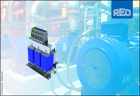
To provide an equally robust, yet more cost effective solution, REO has developed a special filter to overcome interference problems, which are inevitably exacerbated by the use of long cable runs. The 400V three line CNW933 sinusoidal filter range is available in units rated from 2-1200A.
The CNW933 eliminates the need for shielded cable by suppressing unwanted frequencies. This is achieved by an efficient use of various inductance and capacitance solutions, which eradicate harmonic currents, smoothing the peak waveform created by PWM and producing a near sine wave supply. Motor life is increased whilst noise, mechanical stress and thermal conduction are alleviated.
The cost savings of using standard cable can be considerable. In a typical drive installation using a 4kW drive at a distance of 200m from the motor, cable savings alone can be around £100. This means that almost three times as many installations could be cabled using standard cable, as opposed to shielded.
These savings quickly mount up when larger drives are utilised. The saving for a typical 160kW installation is approximately £1500. Considering REOs sine wave filters can be used for cable lengths of up to 1000m, savings for this configuration would reach £7,500.
In a world becoming increasingly intangible, it seems that cabling is yet to be swayed. Despite the inordinate amount of regulatory complexity and financial pressure under which manufacturers operate, it is evident that there are still cost effective measures, yielding longer term return on investment. Maybe next time we’ll pause to think before complaining about that tangled cable.