BRAKING RESISTOR DESIGNS AND APPLICATIONS
Introduction
When a motor is driven by its mechanical load, such as in the case of a decelerating flywheel, the motor acts as a generator and the kinetic energy is converted into electrical energy. Often this surplus electrical energy, if it cannot be regenerated, is unwanted and it can be harmful to the electrical motor drive system. When this condition arises the surplus energy can be absorbed by the introduction of a resistive load into the motor circuit which converts it into heat and at the same time a braking effect is created, which usually is desirable for reasons of safety and protection of the electrical drive system.
Manufacturers of frequency inverters recognise that a braking resistor will be required for some applications and they provide connections to the DC Link to enable one to be incorporated into the system. The control electronics monitor the level of voltage within the DC link and when this rises above a limit, the braking resistor is switched into the circuit by the use of a FET or IGBT otherwise known as a “chopper”. When the DC voltage drops to a safe level again the load resistor is switched out of the circuit.
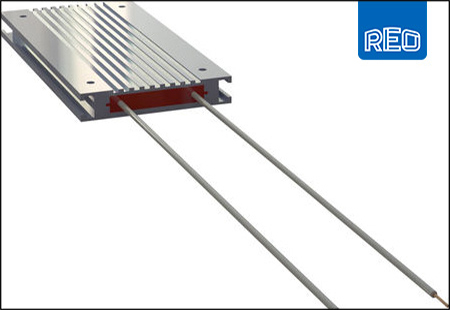
As an example of construction, a braking resistor might have coils manufactured from copper-nickel or nickel-chromium, both of which have resistance values that are constant over a wide range of temperatures. The coils, the number depending upon the units rating, are connected in parallel which means that the load does not rely on a single winding.
For safety and reliability purposes, windings might be embedded in a filler material such as quartz. This would give mechanical stability together with short circuit protection plus self-extinguishing properties. Such fillers also assist with the efficient transfer of heat from the resistor windings to the inner surfaces of the aluminium housing.
Further electrical isolation could be provided by insulation sheets being inserted between each winding and between the resistance winding assembly and the sides, top and bottom of the extruded aluminium housing.
For still further isolation and to provide high ingress protection ratings, the resistor assembly could be encapsulated within a silicone sealant. This technique can allow IP ratings up to IP64 to be achieved; this is useful in environments where installation of the brake resistor within a control panel is unwanted or economically prohibitive.
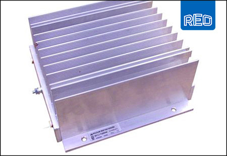
If enclosed in an extruded aluminium housing the housing acts as a heat-sink and quickly dissipates the thermal energy generated by the resistance windings to open air. Special grades of aluminium finishes can be used to give long term durability to all types of atmospheric conditions, including salt spray.
In some cases, power ratings can be increased substantially. For example, fitting a fan doubles the useable power and some resistors actually have special slots to facilitate fan installation.
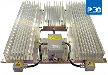
When there is restricted space or if the braking resistor has to be built into a control panel, which has inadequate cooling, then forced air-cooled units have limitations and the solution is to use a water-cooled braking resistor. These can be indirectly cooled by bolting them down onto a back panel that has built-in coolant pipe loops, sandwiched between a double metal skin. The back panel can also be used for cooling other components such as frequency inverters and chokes. Some manufactures can even supply braking resistors that have indirect water-cooling that is an integral part of the resistor assembly.
A more efficient method of cooling is to incorporate the cooling circuit within the body of the resistor itself. Where this is employed, water connections are best located at the opposite end of the resistor body to the electrical connections, which can be flying leads or terminals in a terminal box.
For higher power ratings it is possible to assemble several braking resistors together and then connect them in series/parallel depending upon the required resistance value that has to be connected to the DC link of the frequency inverter (the power and resistance value is normally provided by the drive manufacturer).
Typically, standard resistors are designed to operate at an ambient temperature of around 40OC with maximum coolant temperatures of 25OC in-flowing and 45OC out-flowing. It is important that an industrial coolant or drinking water is used and generally the water should be soft, with no mechanical, chemical or biological contamination. There is a standard; VGB-R 455 P, which applies to suitable coolants.
Thermal sensors can be fitted for monitoring the resistor temperature. When the temperature limits are exceeded the sensor’s contacts open and this is used as a fault signal so that the motor drive system can be brought to a controlled stop.
Application examples
Cranes: When a crane is being used to lower a heavy load it has to contend with surplus potential energy, which could cause the motor to run away in an uncontrolled manner, thus creating a safety hazard. A braking resistor can be used to prevent this from happening.
Elevators & lifts: When elevators and lifts are descending and carrying people there is excess potential energy that tends to drive the lift motor in reverse, thus making it operate like an alternator. A braking resistor can be used to dissipate unwanted electrical energy. There are some purpose-built units for this duty, engineered for roomless lifts and for fitting inside the framework of an escalator. These resistors have special EMC connection boxes which are required in public buildings and can provide protection against dampness and dust. Importantly, this type of resistor does not require additional housing, thus they can be used in confined spaces and usually cost less than enclosed resistors.
Electric locomotives: Dynamic braking resistors are often used in conjunction with air brakes in electrical locomotives to reduce the amount of wear on mechanical components. When it is switched into a circuit the braking resistor causes the current to flow in the opposite direction to when the locomotive is motoring. Therefore, the motor exerts a torque that opposes the forward motion.
Wind turbines: The braking of a wind turbine can be achieved by “dumping” energy from the generator into a braking resistor. This technique is useful if the kinetic load on the generator is suddenly reduced or is too small to keep the turbine speed within its allowed limit. Also, in faster winds, it is possible to introduce cyclical braking which causes the turbine blades to slow down. This increases the stalling effect, thus reducing the efficiency of the blades. In this way, the turbine’s rotation can be kept at a safe speed.
Other applications include automatic assembly machines which have large masses that have to move and stop quickly, and power supplies containing capacitors that have to be discharged for electrical safety reasons.