


Safety of Aluminium Clad Brake resistors
Downloads
| REO2026-3-Safety-of-Aluminium-Clad-Brake-Resistors.docx ( DOCX 240KB) |
| REO2026-03.png ( PNG 440KB) |
| Image-1-Showing-no-Insulation-Material-scaled.png ( PNG 2889KB) |
| Image-2-Showing-gaps-in-insulation.png ( PNG 2315KB) |
| Image-3-Recommended-Mounting.png ( PNG 463KB) |
What’s inside your Braking Resistor?
Aluminium-housed braking resistors are widely used in modern drive systems, yet their internal construction and installation requirements are rarely examined closely. Recent investigative work comparing commercially available units highlights how insulation design, earthing arrangements and the practical effects of surface oxidation can influence the safety and reliability of the overall Power Drive System.
Introduction
Braking resistors are a familiar component in variable speed drive systems, used to dissipate excess energy during motor deceleration. Specifications often focus on resistance value, power rating, and size. However, a closer examination of several aluminium-housed resistors with similar ratings shows that both the internal construction and the installation provisions can vary significantly.
Externally, the units appeared broadly comparable. Internally, however, differences in insulation systems, winding support and earthing arrangements were evident – factors that are rarely visible in datasheets but can influence real-world performance, long-term reliability and impact electrical safety.
Braking Resistors and the Power Drive System
Under EN 61800-3, braking resistors form part of the overall power Drive System (PDS), alongside the drive, motor and associated cabling. This means their design and installation contribute to both systems performance and electrical safety and should be considered accordingly. In other words, the resistor should not be treated simply as an external accessory. Its construction, mounting and earthing all form part of the wider integrity of the drive installation.
Aluminium Housings: Thermal Performance and Safety
Aluminium housings are widely used for their excellent thermal conductivity, which enables efficient heat transfer away from the resistor element. As a conductive enclosure, however, the housing must also be reliably connected to protective earth to ensure safe operation.
In the event of an internal insulation fault, a low-resistance earth path not only helps with EMC issues but also ensures that fault current flows safely and that protective devices operate correctly
Why Oxidation Matters
The key practical issue is that aluminium surfaces naturally form a thin oxide layer when exposed to air. Although extremely thin, this surface film is electrically insulating, with a typical electrical resistivity in the range 10¹²–10¹⁴ Ω·m, and this can cause problems with the quality of an earth bond if the connection relies solely on surface contact, meaning that a resistor enclosure may appear to be securely mounted, yet still not provide an equally secure electrical bond.
In practice, that makes earthing of aluminium housings more dependent on mounting detail than might first be assumed.
Internal insulation and Reliability
The insulation system between the internal resistor winding and its aluminium enclosure is critical, particularly given the elevated operating temperatures. UL-Listed materials are typically used because they are proven to withstand sustained thermal stress and repeated cycling. Variations in insulation design can affect long-term reliability and the risk of electrical leakage.
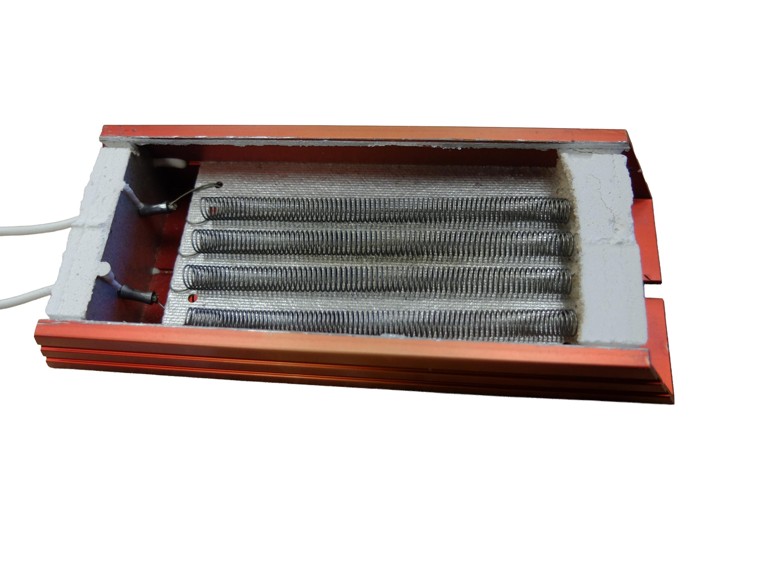
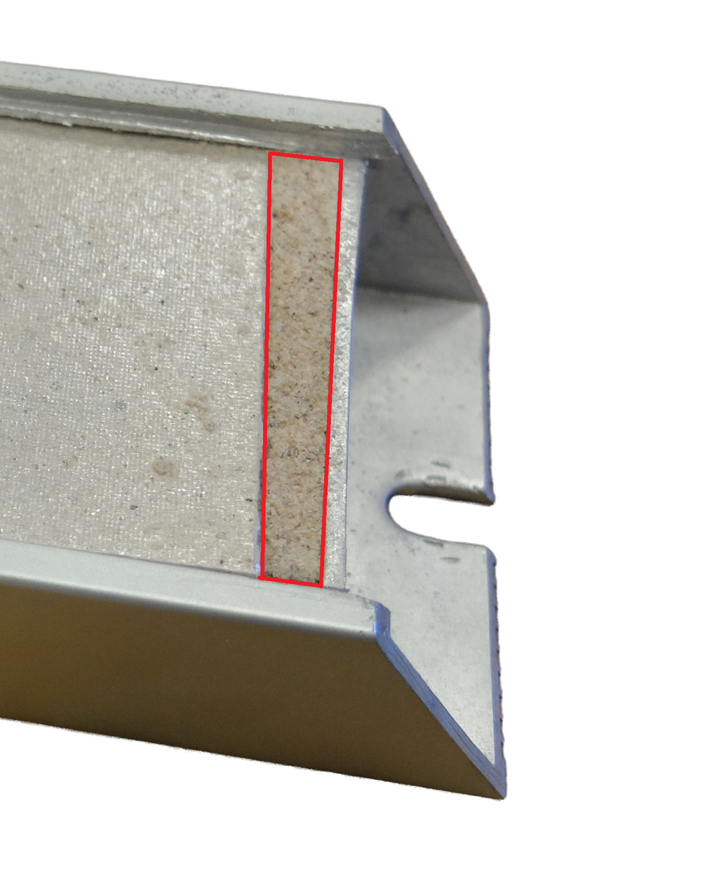
Where insulation is either absent or ineffective, the quality of the protective earth connection becomes even more important to the overall safety of the installation – see Image 1, showing no insulation material and Image 2, showing gaps in insulation.
Installation Considerations for Reliable Earthing
In aluminium-housed braking resistors, achieving a reliable protective earth connection depends not only on product design but also on installation method. Where no dedicated earth terminal is provided, installers often rely on mounting hardware or enclosure contact to complete the protective earth path.
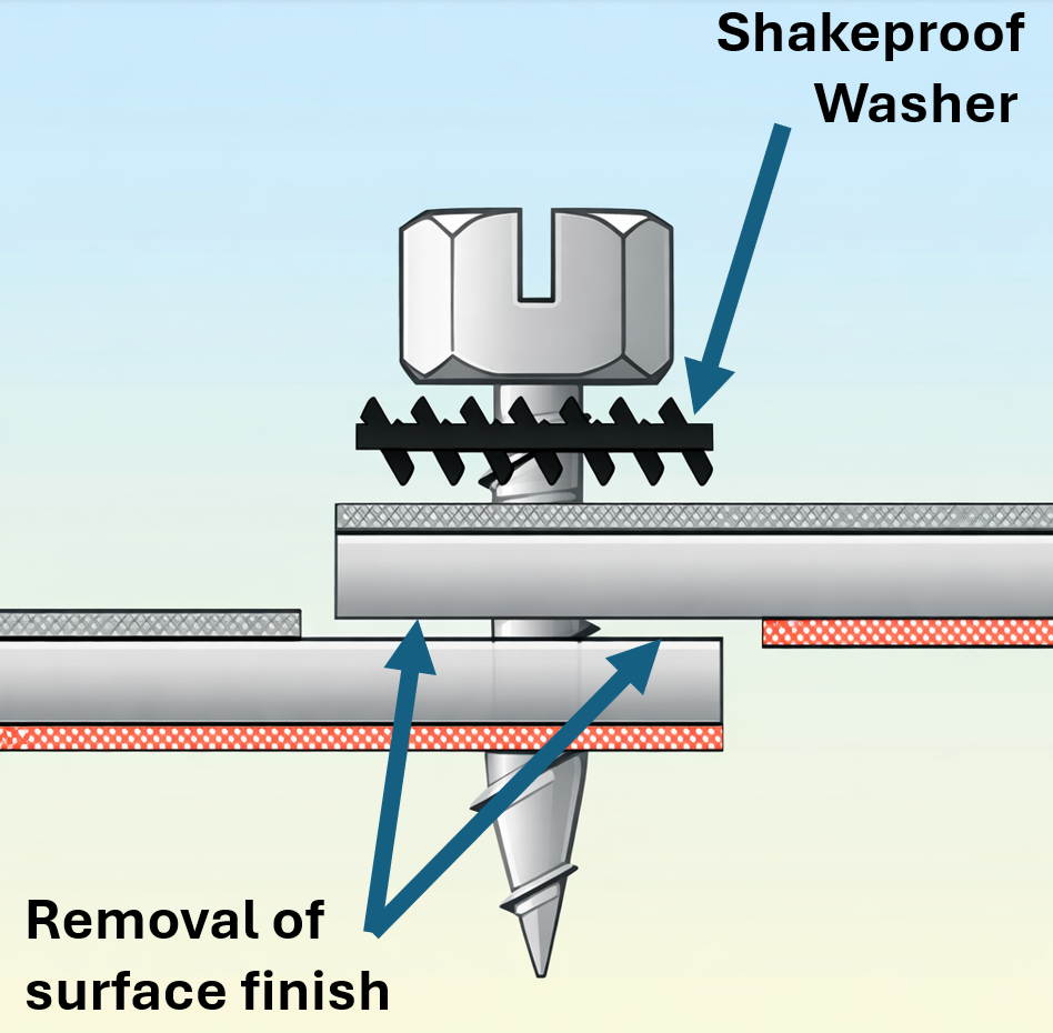
To improve consistency, good installation practice typically includes the use of serrated or star washers, adequate clamping force, preparation of bonding surfaces where required, use of dedicated earth conductors where possible, and avoidance of insulating layers between contact surfaces – See Image 3, showing the recommended mounting.
Thermal cycling, vibration and environmental conditions can all influence the stability of the earth connection over time. In many cases, the effectiveness of the protective earth path is determined as much by installation practice as by the component itself.
Looking Beyond the Datasheet
For engineers specifying braking resistors, this highlights an important point: components with similar electrical ratings may differ in internal construction and installation behaviour.
While electrical specifications remain essential, factors such as insulation integrity, mounting method and earthing arrangements are equally important in ensuring safe and reliable operation. As braking resistors form part of the overall Power Drive System, they should be considered just as carefully as the drive itself to maintain performance and, more importantly, safety over the lifetime of the installation.