


Brake Resistor Technologies: Lessons from the Field


Downloads
| REO2025-34-Types-of-Braking-Resistor.docx ( DOCX 243KB) |
| 1000116607-scaled.jpg ( JPG 369KB) |
| 1000116604-scaled-e1761836548330.jpg ( JPG 464KB) |
| 8J8A4008-scaled.jpg ( JPG 177KB) |
| Figure-2-scaled.jpg ( JPG 695KB) |
| Figure-5.jpg ( JPG 99KB) |
Lessons From The Field
Braking resistors are critical safety components within electrical drive systems, converting excess regenerative energy into heat to prevent overvoltage and protect sensitive components. As energy efficiency and control precision have improved, so has the demand for braking solutions capable of withstanding harsh environments, vibration, and rapid duty cycles.
This article examines three key construction methods – tubular, frame (register or grid), and aluminium clad – exploring their strengths, limitations, and lessons learned from recent real-world applications, especially in the industrial and transport sectors. These have provided valuable insights into how resistor construction affects long-term reliability, safety, and performance.
Tubular Resistors
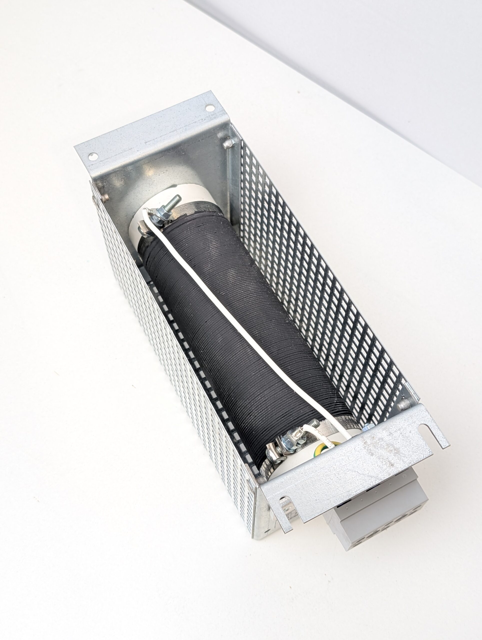
Tubular resistors, see figure 1, remain one of the simplest and most established braking resistor constructions. Built around a ceramic or fiberglass core with resistance wire wound along its length, the assembly is often cement-coated for insulation and rigidity. This design offers simplicity and low cost but also introduces several limitations. Voltage withstand capability is restricted because windings are closely spaced, increasing the risk of arcing under transient or surge conditions. With limited ingress protection – typically IP00 to IP20 – tubular resistors are also vulnerable to contamination and moisture, and can exhibit audible noise in some applications.
In legacy installations, particularly older lift and conveyor systems, tubular resistors are still a common sight; however, exposure to vibration and humidity can cause insulation breakdown, winding displacement, or failure of surface coatings. In one series of retrofit projects, open-tube resistors operating near moisture sources suffered visible corrosion and thermal fatigue within six months of service. The early failures highlighted the sensitivity of this construction to moisture and temperature cycling. While adequate in clean, temperature-controlled settings, they are increasingly viewed as unsuitable for demanding industrial or outdoor environments.
Frame (Register/Grid Type) Resistors
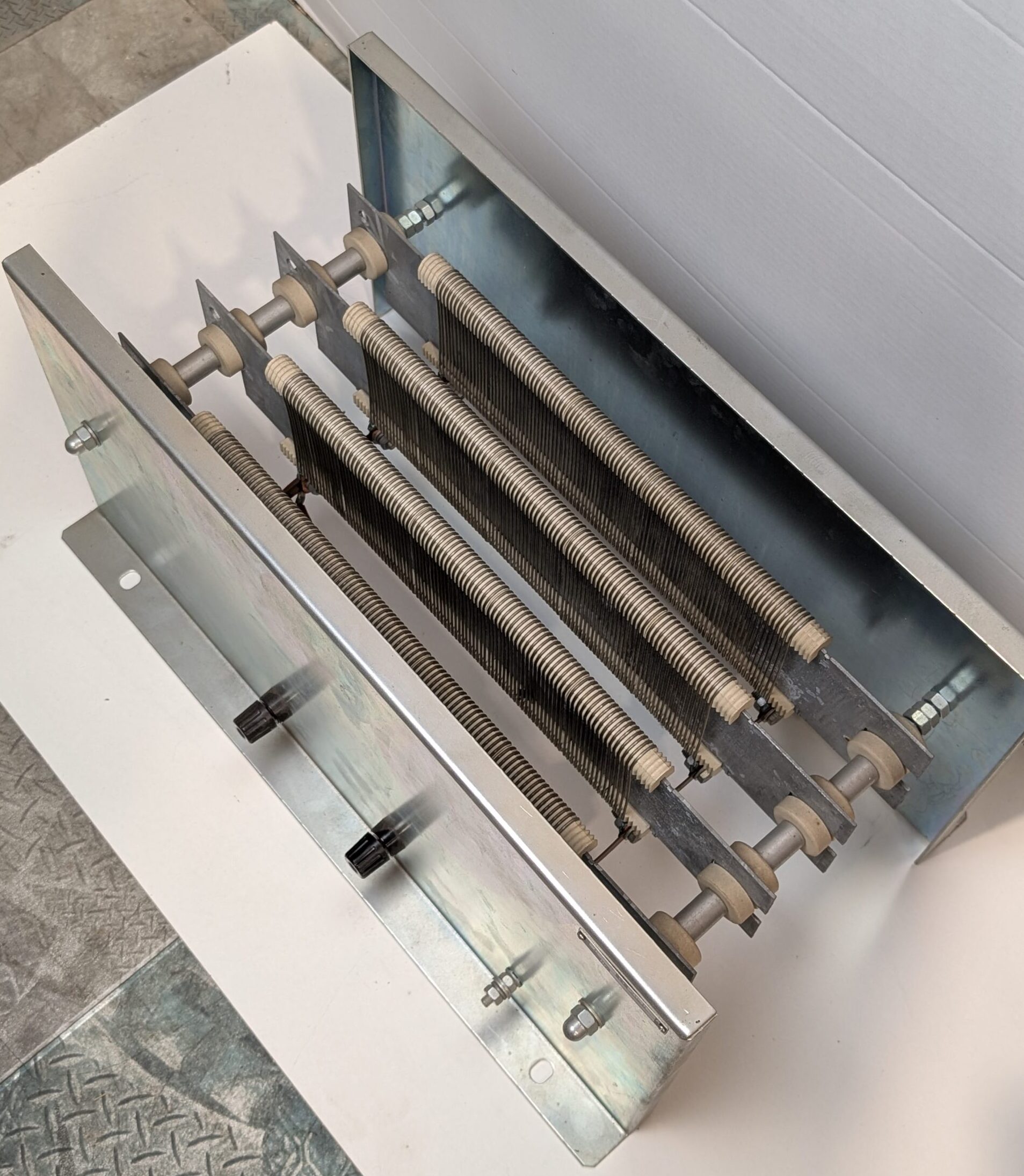
These types of resistors, see figure 2, represent the next step in design evolution; they usually consist of flat resistance elements – often stainless steel or nickel-chromium alloy ribbons – mounted on insulating supports to form a grid. The deliberate spacing between windings improves voltage withstand and allows better cooling airflow. Assemblies can be stacked or configured to meet specific power and resistance values, offering a modular and serviceable solution. They are often used for generator testing and neutral earth applications.
Despite their advantages, frame resistors are still limited by their open construction. Their maximum protection level rarely exceeds IP20, exposing them to dust and moisture. In vibration-intensive settings such as cranes or rail vehicles, the mechanical stresses can lead to failures, and as they are often force-cooled to reduce size, cooling-system maintenance can become a problem.
Nevertheless, frame resistors remain a practical middle ground for indoor industrial drives housed in electrical cabinets. They balance cost and performance, offering modularity and straightforward installation for integrators seeking flexibility.
Aluminium Clad (Encapsulated) Resistors
Aluminium-clad, encapsulated resistors, figure 3, have become the benchmark for reliability and safety in demanding drive and traction applications. In these designs, the resistance element is embedded within an aluminium extrusion and filled with a thermally conductive compound such as quartz or ceramic filler. The result is a sealed, mechanically robust assembly with ingress protection typically from IP20 up to IP66 or even IP67.
Recent industrial products have demonstrated the resilience of encapsulated resistors under harsh conditions. Units subjected to prolonged salt-mist and vibration testing maintain consistent resistance values and insulation strength.
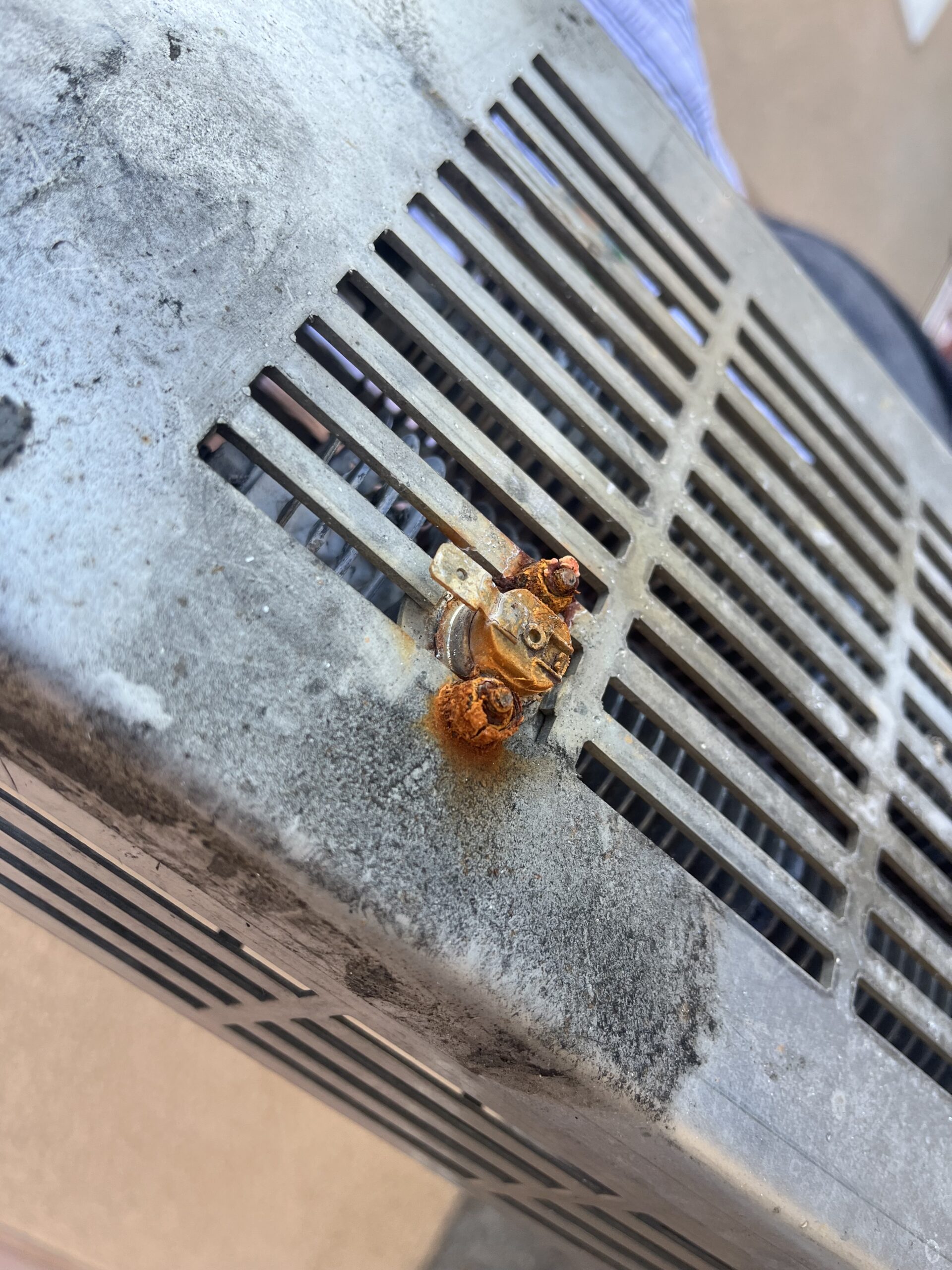
Aluminium-clad resistors also integrate additional safety features such as an embedded thermal switch (see figure 4 for an example of a thermal switch not embedded in an aluminium-clad resistor), allowing early detection of overload or restricted airflow. The encapsulation dampens acoustic noise, which is especially useful in Building Technology applications, and isolates the windings from external contamination, making these units particularly suitable for outdoor drives, rail traction, and renewable energy applications. Their high dielectric strength enables reliable operation at voltages up to 1,000V and impulse loads well above ten times their nominal rating.
Industry Developments and Field Insights
The shift from open to sealed resistor construction reflects broader trends across the electrical drive industry. The adoption of higher switching frequencies, compact enclosures, and mobile installations has increased thermal and mechanical demands on braking systems. Failures observed in older resistor types – cracked ceramic formers, corroded terminals, and non-tripping thermal switches – underscore the need for more reliable solutions.
Many manufacturers have recently adopted rigorous testing regimes that simulate the harsh conditions experienced in rail, offshore, and heavy-duty industrial environments. Resistors now undergo salt-mist, shock, and vibration testing to international standards, ensuring performance consistency and mechanical stability. The incorporation of IP65-rated anodised housings and fully sealed extrusions represents a significant leap forward in safety and reliability.
EMC Considerations and Shielding
Under EN 61800-3, braking resistors form part of the overall Power Drive System (PDS) – the combined drive, motor, cabling, and associated components must meet EMC emission and immunity limits. Open resistor designs and their cabling can act as unintentional antennas, coupling high-frequency noise into surrounding equipment, cabling and metallic structures. This is particularly relevant at the DC link or braking chopper connection point, where fast-switching IGBT edges can generate significant broadband RFI.
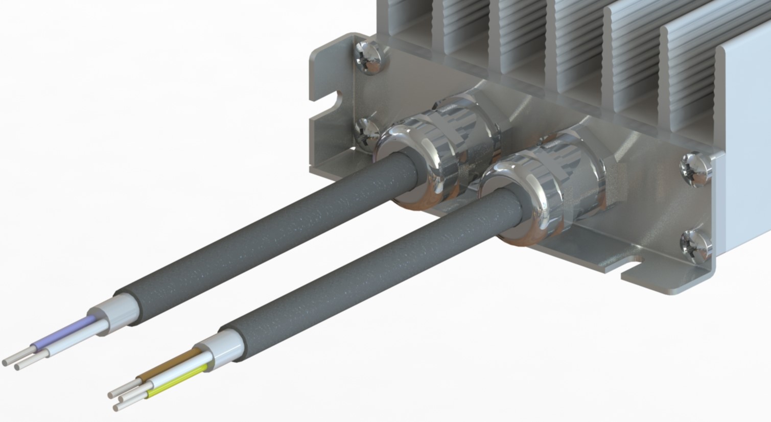
Aluminium-clad, encapsulated resistors offer a clear EMC advantage, the metal housing provides a grounded, conductive barrier that functions as a Faraday cage, significantly reducing radiated emissions, and when these IP65-rated units are installed using screened or armoured cable, and the cable braid is bonded directly to the enclosure with a full 360-degree connection, see figure 5, RFI currents remain confined within the screened path and cannot radiate into surrounding equipment.
While braking resistors are rarely the dominant EMC source within a PDS, proper shielding and bonding at this interface can simplify overall compliance, reduce the need for supplementary filtering, and improve noise immunity throughout the system. This approach is particularly beneficial in rail, renewable energy, and industrial automation environments governed by EN 61800-3 and EN 50121, where strict electromagnetic limits apply. Aluminium-clad resistors with screened cables are often specified in motorised satellite dish and radio telescope applications, where keeping RFI to a minimum is essential.
Comparison and Outlook
When viewed collectively, tubular, frame, and aluminium-clad resistor designs illustrate a clear technological progression. Tubular resistors, though economical, offer limited resilience and are best suited to low-cost, indoor applications. Frame resistors provide improved electrical performance and modularity but remain vulnerable to environmental stress. Encapsulated resistors, while more expensive, especially at high power ranges, offer superior performance, ingress protection, and long-term reliability.
The lessons from recent projects reinforce that the total cost of ownership – rather than purchase price – should guide resistor selection. Where downtime, maintenance access, or environmental exposure are factors, sealed extruded resistors consistently demonstrate better lifecycle economics and safety outcomes. As energy systems continue to evolve, design priorities will favour compact, RFI-benign, vibration resistant, and thermally efficient solutions. The ongoing refinement of encapsulated resistor technology ensures that braking systems remain a reliable and indispensable safeguard for modern automation, HVAC, building technology, and transport.
For more information, please visit https://www.reo.co.uk/brake-resistors/