


REOhm braking resistors
From compact VFD braking to high-power traction systems.
REO braking resistors safely dissipate regenerative energy across industrial drives, traction and e-mobility, with air- and water-cooled solutions for a wide range of power requirements.
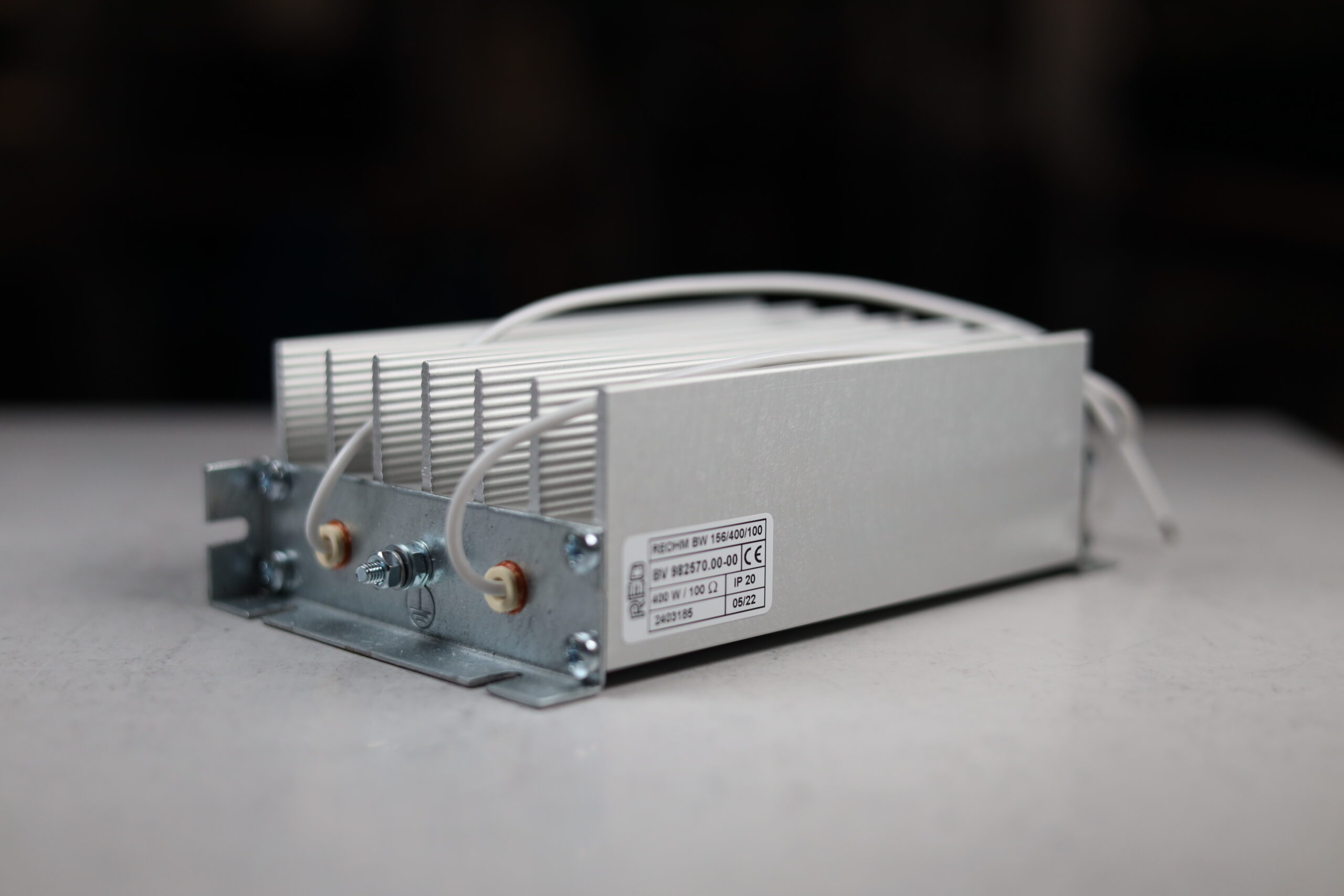
Wide power range
Compact to high-power solutions
Air & water cooled
For different duty requirements
Environmental protection
Options for demanding installations
Application support
Help selecting the right resistor
Product range
Choose by power level, duty and environment.
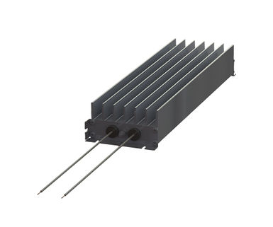
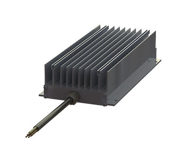
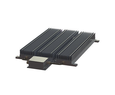
From compact profile resistors for standard inverter drives to liquid-cooled assemblies for traction, e-mobility and high-power systems.
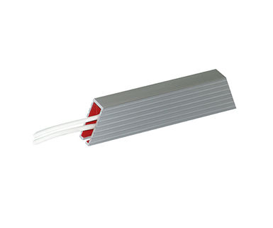
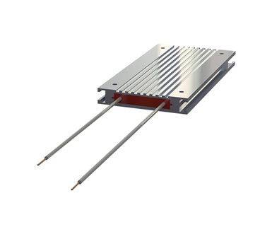
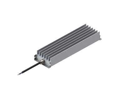
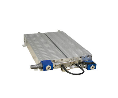
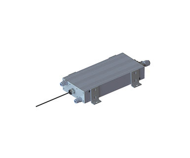
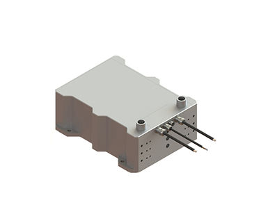
Sizing tool
Not sure which resistor you need?
Enter your braking duty cycle and pulse power to estimate continuous dissipation and identify a suitable starting point in the REOhm range.
Applications
Built for demanding braking applications.
REO braking resistors are used across industrial drives, transport, energy and high-performance electrical systems.
Cranes & hoists
Escalators & lifts
Railway systems
Marine & offshore
Wind & energy
E-mobility & test systems
Engineering insight
Practical guidance from the field.
Useful reading for engineers specifying braking resistors, checking duty cycles or avoiding thermal design mistakes.

Brake Resistor Technologies: Lessons from the Field
Practical field insights on construction, materials and thermal design trade-offs.
Read article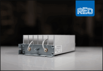
Brake Resistors & REO Reliability: Stock Availability
How stock availability supports OEM schedules and responsive maintenance demands.
Read article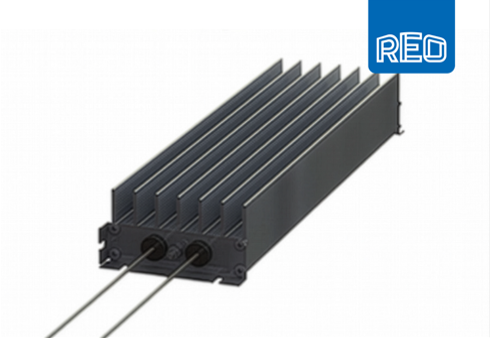
Brake Resistors – Dangers of Poor Design
What can go wrong with undersized or poorly cooled units, and how to avoid it.
Read article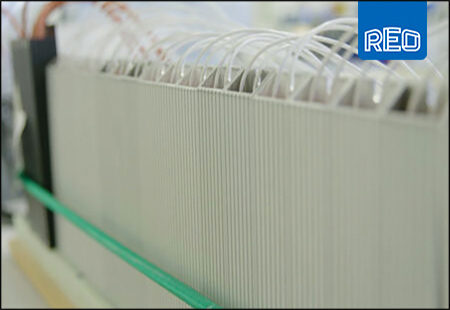
Duty Cycles & Hidden Ratings
Why headline wattage can mislead when intermittent and peak duty are not understood.
Read articleSpecification questions
Frequently asked questions.
Why does braking resistor design matter in modern drive systems?
During deceleration, regenerated energy can raise the DC link voltage. A correctly specified braking resistor gives that energy a safe thermal path, helping protect the drive and maintain controlled stopping behaviour.
Why should I not choose by continuous wattage alone?
Continuous power is only one part of the specification. Peak braking energy, duty cycle, cooling, ambient temperature, mounting position and enclosure ventilation can all change the real thermal load on the resistor.
When should I consider a liquid-cooled resistor?
Liquid cooling is worth considering where power density is high, surface temperature must be controlled, installation space is limited or the resistor must operate in a demanding enclosed system.
Can REO help size the correct braking resistor?
Yes. Send the drive data, braking cycle, resistance requirement, expected energy, ambient conditions and mounting constraints to the REO team for sizing support.
Ready to specify?
Let REO help you choose the right braking resistor.
Share your drive, duty cycle and installation requirements with our engineering team. We’ll help identify the right braking resistor for your application.